![]()
Eddy Current Dyno Feature Comparison
Item |
EC997 | Superflow | Dynojet 200/250 |
| Construction The more solid the construction, the longer the life and the better the data will be. Dyne Chassis Flex will cause all sorts of odd data records. Some of the oddest dyno readings seen can be explained by dyno flex and twist. A Suzuki Hayabusa 1300cc will flex itself before it distorts the EC997 front wheel chock! |
Extremely
sturdy construction. Uses minimum 3/8" plate steel on walking surfaces. Uses heavy
duty structural channel steel for roller / brake framework and the majority of plate
fasteners are 1/2" allens. "Diamond Plate" design is an excellent surface for areas that are likely to experience periodic liquid spills. Diamond Plate is used around the drive roller for safety. "Grip Tape" is used in footrest areas. Sustained oil and antifreeze contact will damage tape. Tape is replaceable as required. Even though the EC997 is constructed of plate steel rather than sheet metal, overall dyne weight is similar to dynojet, as the low inertia drive roller (pat pend) weighs much less than the high inertia drum and allows beefing up of the dyne chassis. |
Sturdy
construction of dyne chassis. Has smooth walking surface but with "grip tape". Tape is replaceable as required. Construction the dyne chassis is of very high quality, but end user "ease of use" is not as highly developed as the construction.
|
Extremely
lightweight dyno chassis is cleverly constructed mostly of bent sheet steel and covered
with thin, lightweight diamond plate aluminum on current models, providing just enough
strength for use. The overwhelming amount of weight present in the complete 100, 150, 200 series dynes comes from the high inertia drive roller or drum. |
| Eddy Current Brake Assembly The mechanical heart of the dyne system. Brake size must be matched to intended use. The better the size match, the quicker the response time and the better the reliability and longevity. Using a 500hp brake is a poor application for 25hp to 150hp test applications. Kind of like using an aircraft carrier to go bass fishing. The point? Use a responsive, high resolution. dyne system, matched to your use to get the most out of your work. |
Very
quick reacting to load changes. Excellent in step and sweep tests. Small diameter, low inertia eddy current brake assembly with a system Linear Mass Rating tm of less than 300# (as compared to 345# or 450#). Uses system similar to Mustang dyne's patented Virtual Inertia System - works best with low inertia dynes. When testing, a "brake" converts power to heat, which must be removed from the brake assembly or the brake will overheat and fail. Air cooled eddy current brakes must be spinning at a high enough rpm to generate enough air circulation to dissipate the heat created while creating load. EC997 and variant systems have been designed with optimal brake rpm vs. load usage windows. |
Large diameter, high inertia eddy current brake assembly. Slower to react to load changes, large diameter, high inertia eddy current brakes are not an optimal application for step or sweep tests. Cannot use quick acting, small diameter brake because it has a 20"
drive roller, turning at too low an rpm while testing - not fast enough to generate enough
cooling air to dissipate the heat created in the eddy current brake assembly - causing
premature brake failure.
|
Large diameter, high inertia, heavy 379lb eddy current retarder
assembly. The large diameter, high
inertia Cannot use quick, small diameter brake because it has a 18" drive roller, turning at an inefficient rpm for the vehicle speed - not fast enough to generate enough cooling air in a smaller diameter brake to dissipate the heat created in absorbing the vehicle power. Especially hampered by an extremely heavy ~800lb-900lb drive roller, which, when coupled with the 379lb retarder causes dramatically increased engine wear when performing step tests. Dynojet had the same problem as Superflow when attempting to use a copy of our small diameter eddy current brake- burnout due to poor cooling due to low rpm caused by the low rpm of the brake. Dynojet still has a problem with brake overheating, as the software will shut down dyno operation when the brake reaches an incredibly high 900f!! (according to K.L. at dynojet). |
Item |
EC997 | Superflow | Dynojet 200/250 |
| Software, Load Control The soul of the dyne system.
|
Very
quick reacting to load changes. Excellent in step and sweep tests. This is due to extremely high data transfer rates for speed and load control coupled to the lowest system total inertia. The bikes that require special settings are low torque / low speed applications, such as cbr250. These bikes require the Small Bike control setting in the software. |
Software
control data rates are sufficient, according to Superflow, but it's observed that high
torque, low speed vehicles seem to be difficult to control.
|
Insufficient
control system makes it impossible to control the load as well as the EC997 series,
causing excess engine wear due to heat buildup - the result of the dyne taking too long to
stabilize at a particular rpm point (as in fuel injection mapping.
05/06 |
| Dyno Calibration | Software
is specially designed to be user friendly. Easy to calibrate, with step by step instructions built into every EC997 Software Package. 2 minutes to do. Open Calibration Screen. 1. Click "Zero". Done. Simple. Do it every month or so. We build dynamometers that will be useable 50 years from now. |
Calibratible by
user.
Power readings are consistent between different Superflow dynos, as long as the dyno is set up to display the True HP figures. In the Superflow software, there is the ability to modify the True numbers, after they are recorded. Unfortunately, you can't tell if the dyno owner is using modified or True HP figures. |
Not
user calibratible. Inertia values are done at dynojet ("each individual Dyno is accurately calibrated for inertia mass, bearing and air drag") As your roller surface wears, the bearings wear and develop friction and the knurled drum surface gets worn smooth causing less air drag the calibration needs to be updated to current dyno conditions. That partially explains why it's not usual to be able to expect any closer than +/- 5% to 7% consistency between different dynojet dynos. Look at Cycle Canada's and Roadracing World research on that. But if you don't care about that - go ahead and buy one! |
| . | . | . | |
Item |
EC997 | Superflow | dynojet
250 |
Drive Roller Where power leaves the vehicle and enters the dyne system. A critical junction point. The drive roller is also a major part of the total system inertia, the defining factor of repeatability and flexibility of the dyne system. Low Inertia Dyne Systems are able to see more detail, are more responsive to power changes and repeatable than high inertia systems.
|
<12.7" ULTRA LOW INERTIA, Patented, Drive Roller with excellent traction. |
Uses 20" drive roller with HIGH INERTIA value. |
Uses an extremely heavy 18" drive roller with very HIGH INERTIA value - perhaps twice that of Superflow and 3x-4x that the EC997. This roller was designed for inertia testing and should not be used on an eddy current system. |
|
PATENTED
ULTRA LOW INERTIA drive
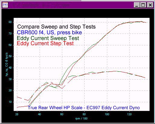
roller Excellent detail in power graphs, will actually show small areas of only 1 of 4 cylinders missing that high inertia systems bulldoze through. Allows creating of real world loads, quickly - like the load experienced at 60mph in top gear. Click here for a
view of a standard resolution view of a sweep test with very fine high rpm detail of a
stock '99 CBR600F4 showing the carb tuning problem from 11.5k to redline. This indicates
that power will be improved up to ~2-3hp at high rpm with CRB-H72-1.7-RK RaceKit Carb
Recal Kit. |
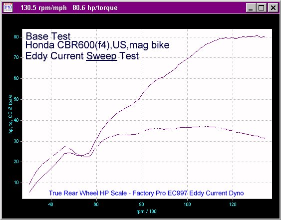
High Inertia
values prevent acquiring fine detail in sweep tests, making fine tuning detail unseen and
unlikely to improve. Low Inertia systems eliminate this "power averaging" effect of high inertia systems. If you are used to looking at only low resolution graphs, check out the sweeps here. Click here
|
Extremely
high inertia values in the Dynojet 200/250 causes greatly increased engine wear when step
testing - the engine must be be sped up to each rpm, effectively doing a fully strained
sweep test to each measured rpm point when step tests are done correctly. Low Inertia systems avoid this problem with less mass to move, showing more detail. Dynojet's very high inertia degrades and even prevents fine detail in sweep tests, making fine tuning detail unseen and unlikely to improve. If you don't see the problem on the graph- there is no tuning problem. Look at the graph.... |
|
|
Patented ULTRA LOW INERTIA drive
roller Ultra Low inertia values allow very descriptive graphing - showing as low as one cylinder missing on a four cylinder engine. Controlled Load Tests OR Controlled Acceleration Tests are available. |
Higher Inertia values prevent acquiring fine detail in sweep tests, making fine tuning detail unseen and more difficult to improve and optimize. | Extremely
high inertia values in the Dynojet 200/250 Load Control dyno mask fine details and hide
areas in the power band that could be improved. Additionally, the high inertia makes it more difficult make fine adjustments in braking force control when compared to a low inertia system. |
|
Item |
EC997 | Superflow | dynojet
250 |
| Drive Roller
Traction Where power leaves the vehicle and enters the dyne system. A critical junction point. The drive roller is also a major part of the total system inertia, the defining factor of repeatability and flexibility of the dyne system. Low Inertia Dyne Systems are able to see more detail, are more responsive to power changes and repeatable than high inertia systems.
|
3. Traction: Patented drive roller, for all intents, eliminates uncontrolled slippage of the rear wheel, even when wet. With the
patented drive
roller, a minimal amount of downforce is required, often as little as bike weight only. |
3. Traction: Simple knurled drum on Superflow drive roller requires excess downforce for traction. According to users, traction is an issue with even 1100cc bikes. Excess downforce is required for traction, causing "compression induced" tire deformation and heat buildup in step tests or extended sweep tests. |
3. Traction: Simple knurled drum on dynojet requires excess downforce for traction. It's well known that traction, without high excess downforce is a major problem on dynojet dynos with worn rollers with even good 750cc supersport race bikes having problems with uncontrolled slippage. Australian users report that using VHT traction enhancer improves traction. Excess downforce causes tire deformation and heat buildup in step tests or extended sweep tests. 05/15/01 |
| 4.Operator location during test: Specially designed to NOT REQUIRE operator to sit on bike. Even if you chose to sit on the bike, it's only 12" off the ground. 6" to 8" lower and safer than other dynes. Stand or sit in chair to the right of the bike allowing access to the throttle, computer keyboard and mouse. Safer for tester and looks much more professional to consumer. Saves time for tester and narrows window of liability for dealership owner. Factory Pro designs dynamometer systems for maximum user
productivity and |
4. Operator location during test: Tester generally boards the bike, all the while balancing the remote control box while testing - exposing tester to possible injury from falling from straddling a bike on a narrow platform, 20" off the ground. Requires remote mount of monitor and an additional remote control input box. Adding cost, extra cables snaking across the dyno room, complexity and the probability of damage to remote control box at some time while handling from dropping. |
4. Operator location during test: Tester mounts bike while testing - exposing tester to possible injury from falling from straddling a bike on a narrow platform, 18" off the ground. Requires cumbersome remote mount monitor that impedes work on the bike while on the dyno, and an additional remote input to start and stop tests. Adding cost, complexity and the probability of damage to remote and cables during handling from dropping. |
|
Item |
EC997 | Superflow | dynojet
250 |
| Drive Roller Offroad knobby tires Where power leaves the vehicle and enters the dyne system. A critical junction point. Low Inertia Dyne Systems are able to see more detail, are more responsive to power changes and repeatable than high inertia systems.
|
5. Offroad knobby tires: Street tires, RR slicks (except "Daytona tires"), knobby tires are all OK to use. In fact, knobby tires have excellent traction on our drive roller. Factory Pro Software delivers extremely smooth data streams, producing smooth graphs on properly tuned vehicles.
And, no, |
5. Knobby tires: It is recommended by users to change to street tires to test off road bikes with knobby tires - effectively cutting out that part of the retail tuning market. Traction, when possible, requires excess downforce and distorts the knobs, and, not uncommonly, weakening and tearing them off. |
5. Knobby tires: According to users, like White Bros, Change to street tires to test offroad bikes with knobby tires As related to customer by Dynojet (at Indy Trade Show 1999 from Paul Langley) Dynojet dynos cannot consistently record accurate data with knobby tires. Same tire problems as other large diameter drive rollers. |
Item |
EC997 | Superflow | dynojet
250 |
Cooling Systems
|
6. STD Fan Setup Testing over the last 6 years of fan systems, we have evolved the best, most cost effective setup available. Our STD High Pressure Cooling System is individually switched and 110 vac. Doesn't affect vehicle power like current integrated fan systems. |
6.
Integrated Fan Setup Superflow's integrated fans, while producing wonderful amounts of high air volume and velocity, are not easily disabled for high speed, low hp applications activated have several other application issues. |
6. STD Fan Setup A low pressure, low velocity squirrel cage fan, mounted high on the front wheel chock is mounted to cool the engine and the exhaust system. Physical location of fan is poor, cutting visual path across dyno room and is a potential "head knocker" when adjusting wheelbase setting on dyno. Air output is weak as compared to other dynos, with only a 50mph velocity claimed. |
| Cooling System Air Supply Our fan system is easily setup to pull cool, clean, outside air into the dyno room to cool the vehicle in the proper places and to assist in dyno room air transfer.
|
Cooling System Air Supply Preheated cooling air Cooling air is drawn into the Superflow air cooled eddy current dyno chassis from inside the dyno room, where heat builds up, despite efforts to prevent it. A well designed dyno room may not build up much heat as the test proceeds, but, with proper rooms having 10-30hp worth of air transfer equipment and air inlet ducting and diffusers, they are not your typical mc dealership setups. So, the fans are usually blowing a large quantity of preheated air at the bike to cool it. Creates less than optimum conditions for repeatability. |
Cooling System Air Supply Preheated cooling air Cooling air is drawn into the fan inlet from the dyno room, preventing more efficient cooling that would be available if using cooler outside air. Same problem as Superflow, with far less air supplied and at a lower velocity. |
|
Item |
EC997 | Superflow | dynojet
250 |
| Engine
Cooling Systems
|
Air outlet duct direction The Factory Pro STD High Pressure Cooling System is typically radiator height and requires a meager 16" square dyno room footprint each. Easy to maneuver, these high powered fans feature easy to direct, adjustable outlets to fine tune air direction for maximum cooling. The multiple fan setup is portable, individually switchable to prevent over cooling and "pointable" at single cylinders, v-twin cylinders, inline 4's - air cooled and water cooled and the specific requirements of the vtr1000, in fact, everything that we have tested, including RS250's and TZ250's (Feb. RoadRacing World) |
Air outlet duct redirection Problems with modified ducting Engines need air ducted to desired locations for cooling - air ducts don't cool if they don't point to the correct location. Power required in an air supply / delivery system is absolutely affected by ANY change in ducting. If the dyne system doesn't monitor and correct for power required by dyno roller powered integrated fans, any change in ducting will cause more error in the hp figures.
Many bikes need additional ducting to direct cooling air causing errors in reading. This example is reducted and reduced to a smaller diameter tubing. |
Air outlet duct direction Air flow direction is directable to a limited extent. |
| Wind Speed Linearity: With our standard High Pressure Cooling System, the fans are not intended to be used to duplicate road speed wind, unless you want to ~75 to 80mph.... |
Wind Speed Linearity: In general, fans just do not increase velocity at a linear rate as speed increases. The actual rate of wind blown will not be the amount that simulates road speed, except for at some particular roller rpm / speed. If you get 50mph wind velocity at 50mph, don't expect to get 100mph wind at 100mph. So, if you are doing pressurized air inlet testing, it isn't correct. |
Wind Speed Linearity: Not applicable, not the intended use of the cooling system. |
|
Item |
EC997 | Superflow | dynojet
250 |
| Engine
Cooling Systems Air inlets and pitmount dyno Exhaust system cooling features
|
Air inlets and pitmount dyno Not an issue, air inlets are not integral to dyne chassis. Bury away!
|
Air inlets and pitmount dyno If you decided to negate the ~20" height issue by installing the dyne chassis into a pit, the air inlets will be below the surface of the floor, causing more intake restriction, and unless there is min. ~6" open area around the air inlet holes, you'll affect the vehicle power recording. The software would need to have the load change data and automatically adjust for increased intake restriction and the lessened fan loading will cause the vehicle hp figures to be increased by the amount of lessened load now produced by the fans. That would make your dyno read high. |
Air inlets and pitmount dyno Good idea to install 18" high Dynojet dyno in a pit. Makes it easier to load. Air inlets are not an issue, as fans are not integral to dyne chassis base. |
| Exhaust system cooling feature Our high pressure / high velocity cooling fan set can be properly aimed at most parts of the bike, making cooling the exhaust system a non-issue as far as this application. |
Exhaust system cooling feature Additional integral ducts for exhaust system cooling? As installed on Superflow, they blow hot air upwards, past some exhaust systems and towards the air intakes of many bikes. Most people don't actually measure actual air temp inside the airbox, they measure general air temp blowing towards the bike, so unless you measure airbox temps inside the airbox, the power readings will be incorrect. At any rate, repeatability is compromised, as tuning changes with air temp. A proper way to cool an exhaust system is to blow from above, blow back and down - away from the air inlets. |
Exhaust system cooling feature The permanently mounted squirrel cage fan, mounted high on the front wheel chock, has limited ability to direct air supply to cool exhaust systems. |
|
Item |
EC997 | Superflow | dynojet
250 |
Integrated
EGA (exhaust gas analyzer) system All measurements are automatically entered for you. Absolutely required to attain Factory Pro level accuracy. (The lower trace is CO% on the example) |
Integrated
EGA (exhaust gas analyzer) system All measurements are automatically entered for you. Absolutely required to attain Factory Pro level accuracy. (The lower trace is CO% on the example) |
||
| ......IN PROGRESS..... | |||
Factory Pro Tuning Procedures
|
No pictures. part of the DataComp Software Package. |
||