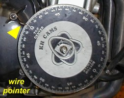
Camshaft Lobe Center Measuring


Install your degree wheel and pointer.


cam deg 01,wheel install.jpg (368347 bytes)

cam deg 01,wheel install.jpg (16067 bytes)


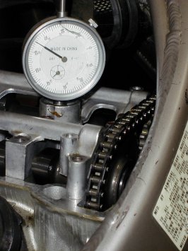
Install your TDC Dial Indicator with special holder installed into spark plug hole.

This shows a 2" travel Dial Indicator installed in the #4 cylinder.

Note: Degree wheels slip on their adapters and pointers get bent!
A dial indicator is a much more versatile device for measuring and rechecking your degree wheel settings. You will leave the indicator installed during the complete cam timing procedure.
Every time that you turn the engine over, you have the ability to recheck you TDC setting.

You can use a dial indicator on an engine that has a vertical spark plug hole. For other types of engines with angled spark plug holes, you will need to use a "positive stop" procedure instead of a dial indicator. Most Japanese 4 or 5 valve sportbikes have vertical spark plug holes.
Most 2 valve engines have angled spark plug holes.
If there is any doubt, use a "positive stop" to set TDC. You won't be able to recheck your TDC settings easily or as often.


cam deg 02,DI TDC.jpg (247204 bytes)

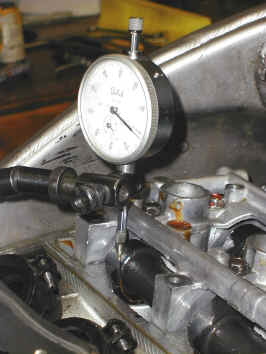
Install your 1" travel Valve Travel Dial Indicator with special tip installed.

This shows the 1" Dial Indicator installed on the #1 cylinder's intake.

If you use cylinder #1 or #4 for TDC, you can use either cylinder #1 or #4 for Valve Lift.
If you used cylinder #2 or #3 for TDC, you can use either cylinder #2 or #3 for Valve Lift.

Special tips? They are flexible and point around corners.

To make:
Gas weld / tack a 2.5" length of 1/16th welding rod onto the tip of a spare screw-on tip for your dial indicator. If you purchase a "Dial Indicator Tip Kit" for ~$20, you will usually find several tips that you'll bet you will never use.
Screw the modified adapter tip into the dial indicator shaft and mock assemble the indicator so you can see the dial indicator face and then to figure out how you need to bend or shorten the extension. When bending the extension, be sure to use 2 pairs of pliers on the extension only, so as to not damage the original indicator shaft.


cam deg 03,DI valve lift.jpg (239423 bytes)

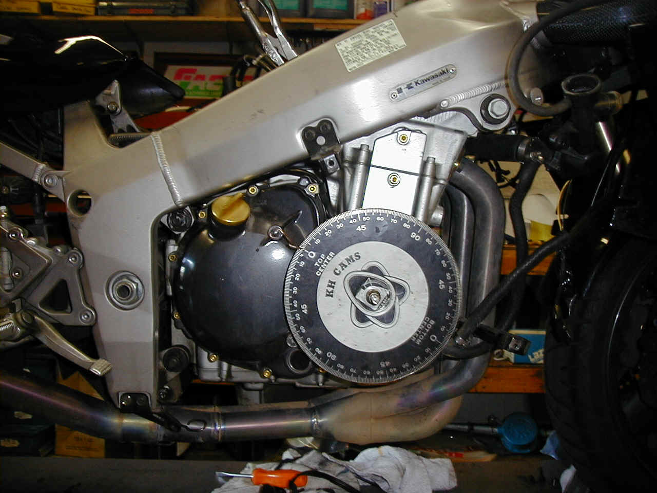
Measure and calculate Intake Cam Lobe Center setting.

Generally, when referencing and optimizing the same set of cams, you will use the Lobe Center method for measuring cam location as referenced to crankshaft location.

Rotate the crankshaft in normal engine direction.
When the intake valve lift reaches exactly .040" valve lift movement, record the crankshaft degree wheel reading. It must be before TDC, between +1 and up to ~30 degrees Before TDC (or the math becomes difficult).

If the measured intake opening at .040" is after TDC, restart measurement and use .030" or .020" lift.  Make sure that you use your selected lift for all measurements on this project.

Differences in L.C. numbers are (generally) minimal at .010" to .050" lift on shim and bucket motors but it's best to not gamble with accuracy.

After you do intake opening, next record intake closing (at the same lift number). That's where you find out what the little "overall travel" dial on the dial indicator is good for. Check and make a note at where the "little dial" is when the intake valve is fully closed. You may just decide to reset the indicator so that the overall travel is at 0 with the valve fully closed and start over on the intake opening again!

Record:
Intake Opening
Intake Closing

Calculate as at left
Intake open degrees, plus
Intake close degrees, plus
180 (180 is a constant), equals
Total Duration

Take Total Duration, divide it by 2 (2 is a constant)

Take Total Duration/2 and subtract Intake Opening number (which will be the smaller of the 2 intake lift numbers that you've recorded - unless the cams are WAY far off!)

When done, recheck your TDC / degree wheel setting. If wrong, reset and redo your Lobe Center measurements. (If you are using the TDC Indicator, you would have checked your TDC / degree wheel settings throughout your previous set of valve lift measurements)

You have your Intake Lobe Center

Lobe Center (AKA L.C.), Method works well when you are comparing the same cam set only. If you were using a different cam duration or lift, the optimum L.C. for one type of cam will NOT be the same as the different cam.


.040" lift, Intake open (IO)=
.040" lift, Intake close  (IC)=


Divide Total Duration
by 2


Subtract IO from
Total Duration


+__________
+__________

+180
=Total Duration @ .040" (or .030" or .020")


Total Duration/2
=__________


(Total Duration/2) -
IO = Lobe Center

=__________ L.C. Intake

For Exhaust Cam:

Repeat.

The only difference is that you will subtract the Exhaust Valve Closing Lift measurement instead of the Opening (as you did on the intake cam) measurement. The number that you use will, like the Intake Cam measurement, will be the "smaller" of the 2 measured opening numbers.

You could say:
Valve Open + Valve Close + 180, divided by 2 and subtract the "little" number for the Lobe Center.

Also, the exhaust cam is typically more difficult to setup the Valve Lift Indicator on when setting and testing in the frame. You may have to rebend the extended indicator tip.

Now!

Example:

The intake valve Intake Opens at 25 degrees Before Top Dead Center (BTDC) - then the piston travels 180 degrees to Bottom Dead Center (BDC), then the piston travels UP, on the compression stroke and at 55 degrees after BDC.

Add up all those numbers. 25 + 180 + 55. Write it down!
That's 260.

Any time you are using this cam and the same "opening lift", you'll always get the same total duration number - in this case, 260. Always check that you get the same total number - or you have made a mistake in reading the degree wheel (very common, at first!)

Now - divide that 260 by 2. That's 130.

Now, finally, subtract the "smaller number", in this case, 25.

You'll get 105 for a lobe center number.

.
. .
. .

Remember! These are hints only. You are responsible for whatever you do with this information.

If you use this information and it helps your application, please contact Factory Pro with results. Thanks, Marc


Absolutely NO carb parts sold in California.

New and improved Suzuki Teka SFI  2

with new TPS display and "MMT" Memory Module Tuner

Finally - Quick, easy, cost effective Suzuki tuning with no expensive "add-on boxes"
Suzuki cruisers and sportbikes

Please click here for more info

Contact Factory Pro
M-F, 9am - 5pm, Pacific time, -7 or -8 GMT

800 869-0497
 USA and Canada

415 883-5620

parts information
 info@factorypro.com

EC997 dynamometer information
info@factorypro.com

Product Support /Tech SECTION
click here


Mailing / Shipping address:

Factory Pro
101c Roblar Drive
Novato, CA
USA

And most importantly
Restart back at the HOME page and click on the red box in the top left to find the bike that you want parts for...
restart at HOME page


This Tuning Site has been visited by
  
people.
www.digits.net - the oldest counting service on the web


LINKS
EFI and Carb Tuning - Most all FI and carb tuning

by Wheelsmith Racing

Flight Training - train with AMA race winner Todd Harrington.

The Harringtons own American Flyers, one of the most established flight training facilities in the USA.

 8 locations

 800-362-0808
The Rich Oliver Mystery School will help you discover your hidden inner strength. 
It will challenge you. It will teach you a new way of thinking, and a new way of riding. You can take your riding to an exciting new level!  

We use a variety of proven drills and training techniques. 
Practicing these techniques with our Yamaha dirt track trainers will enhance your abilities both on the track or the street.  

It doesn't matter what you ride or race, the Rich Oliver Mystery School improves everyone's skill level and mindset!

WW2 vintage flying Special

Book a sightseeing flight over the Wine Country or a Kamikaze aerobatic flight or a biplane flight over famous Sonoma Raceway, the Golden Gate Bridge and the San Francisco Bay for one or two during the spring and get a free souvenir t shirt!
(NEW!  Ask about the P-40 flights!)

707 938 2444

Just tell them that you saw this on the Factory Pro website!
Marc
Northern California's most unforgettable flying experience.  No experience required.  Open weekends!

The extension of the laboratory for engines of the Swiss Federal Institute of Technology was completed in about 1935. Its architect was Rudolf Otto Salvisberg (1882-1940). He had a successful career in Berlin but returned to Switzerland after the advent of the Nazis. His architectural style was somewhat similar to that of Erich Mendelsohn. The staircase of the laboratory is in normal use but well preserved.
Edited to the tunes of Chemical Residue by Herbie Hancock.