![]()
Dyno assembly
EC997 Dyno System Contents:
| Item | models / desc |
how to connect cables to PAU box.... |
|||
|
PAU Power Supply Box Requires
220
volt, single phase, 10 amp or 110 volt, 30 amp |
App Description Function
|
|
|||
|
LH cable: Large, round 9 pin connector, small gray cable, 9 pin serial connector on back of "Black Box". |
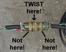
Middle cable: Small round, 3 spade 3/4" black rubber cable to eddy current brake power terminal strip.
|
RH cable: PAU Power 3/4" black rubber cable, Hardwired inside PAU Power Supply Box - the other end connects to 110vac 30 amp. circuit.
Use "Twistlock" type plug |
|||
| Item | models / desc |
how to wire PAU Box and EC brake for power... |
|||
|
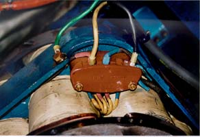
Brake Power Supply Cable
|
App Description Aprox. 20 feet in length. (Sometimes preinstalled) |
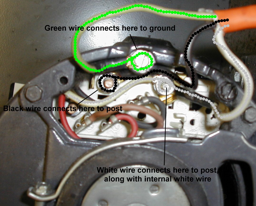
0-90vdc wire diagram: Connect as shown. |
|||
|
Green is the ground
wire and is attached to the eddy current brake frame. |
Middle cable goes
to |
||||
| Item | models / desc |
GREASE |
|||
|
EC Brake |
App |
No need for now, but every December 31st and June 30, grease the brake. Use only |
|||
| Item | models |
how to connect load cell and speed sensor... |
|||
|
Load Cell and |
App
Warning
Note |
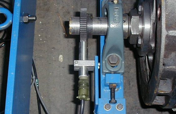
1. There will be
a dummy spacer in the load cell location (at the EC brake) during shipping.
Remove it.
5.Connect male screw-in connector on black speed sensor to female connector on the gray main harness. |
|||
| Item | models |
how to set clearance on speed sensor... |
|||
|
Speed Sensor
clearance adjustment |
App all eddy current and inertia dynes |
|
|||
| Item | models |
how to connect Speed Sensor cable... |
|||
| Speed Sensor cable |
App all eddy current and inertia dynes |
Attaches
to the gray "Siamesed" cable. One side of the siamesed cable is a larger,
25 pin connector that goes to the back of the "Black Box".
|
|||
| Item | models |
how to connect connect sensor cables and computer and Black Box together... |
|||
| Black Box connect |
App |
|
|||
| Item | models |
how to wire fans for power... |
|||
|
Fans, std package w/ 1hp, single phase motor |
App |
110 vac single phase wiring
diagram, below |
|||
|
|
|||||
True Rear Wheel HP measurement on the EC997!